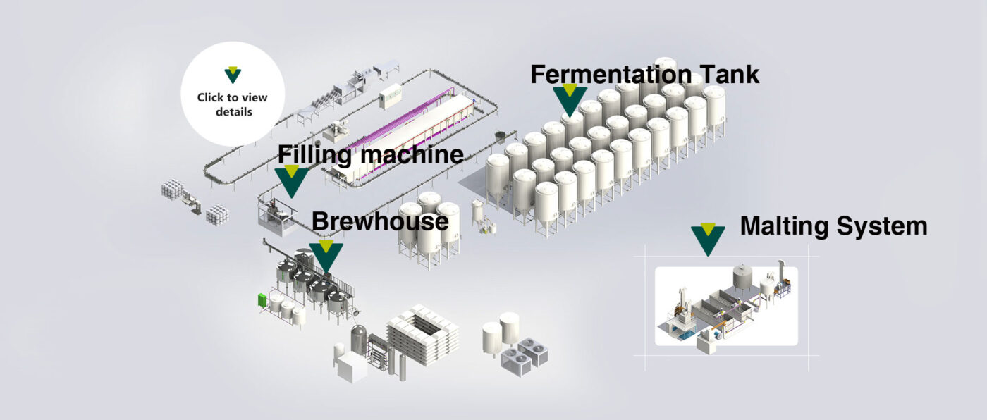
A turn-key brewery is installed in a fixed engineering sequence: building verification, vessel placement, sanitary piping, utility connection, electrical work, automation checks, CIP commissioning, water trials, and production testing. A 10–50 hL brewhouse may require dozens of sanitary connections plus steam or electric heating, glycol, compressed air, CO₂, treated water, drainage, and power. CIP pipelines commonly operate around 1.5–3.0 m/s, while Alfa Laval guidance describes typical caustic cleaning near 2–2.5% depending on the application. Installation ends only after pumps, valves, instruments, heating, cooling, cleaning cycles, and brewing sequences have been tested together under site conditions.
The process starts with the building rather than the tanks. Engineers compare the approved equipment layout with actual floor dimensions, ceiling clearance, door openings, drainage locations, electrical service, water supply, ventilation, and utility entry points. A vessel that fits on a drawing can still become difficult to install if a doorway, roof beam, floor drain, or service platform was positioned differently during construction.
Floor condition matters because tall fermenters place substantial weight on relatively small leg areas. Installers confirm that the slab, anchors, and equipment feet match the structural plan, then check enough overhead space for valves, spray devices, instruments, and future service. Equipment locations should also leave practical access around manways and removable pump or motor components.
That survey determines the unloading sequence. Large tanks normally enter first because smaller pumps, platforms, pipe racks, and electrical panels can be installed around them later. A 20 hL fermenter may hold roughly 2,000 liters at nominal volume before headspace and vessel geometry are considered, so rigging plans must follow the tank manufacturer's lifting instructions rather than relying on capacity alone.
Tank position affects nearly every later trade. Moving a fermenter after glycol headers, product piping, cable trays, and platforms are installed can require several systems to be dismantled.
After rigging, the brewhouse vessels are leveled and aligned. A typical installation may include a mash vessel, lauter vessel, kettle, whirlpool, hot-liquor tank, cold-liquor tank, wort heat exchanger, pumps, grist equipment, and operator platform. Compact systems may combine two brewing functions in one vessel, while larger plants separate them to increase scheduling flexibility.
The installer then connects the beer brewing equipment according to the approved process and instrumentation drawings. Product routes are checked against valve orientation, pump suction direction, heat-exchanger connections, tank outlets, sample points, and cleaning returns. A piping connection that is mechanically correct can still create operating problems if it leaves liquid trapped after transfer.
Sanitary piping therefore receives more attention than ordinary utility pipe. Product-contact lines should be arranged for cleaning and drainage, with branches kept short where possible and serviceable valves placed where operators can reach them. Pipe diameter is selected from required flow, pressure loss, pump capability, and cleaning velocity rather than from tank size alone.
For CIP, Alfa Laval's 2024 pump handbook cites an internationally accepted pipeline velocity range of 1.5–3.0 m/s during cleaning phases. The same handbook notes that cleaning performance depends on time, temperature, chemical concentration, and mechanical flow conditions, so a large pump alone does not establish an effective cleaning circuit.
Weld quality is checked before insulated lines or wall penetrations make inspection difficult. Product-contact welds should have smooth internal transitions and no accessible crevices that can retain wort, yeast, or cleaning solution. Where the project specification requires hygienic orbital or manual welding, the contractor follows the stated procedure for shielding, inspection, cleaning, and passivation.
Utility work follows the process piping because every production vessel depends on supporting services. The installation scope may contain several independent systems:
-
Heating: steam, electric elements, or another approved heat source for brewhouse vessels.
-
Cooling: glycol supply and return for fermenters, bright tanks, wort cooling, and other designated users.
-
Gas: regulated CO₂ and, where required, compressed air or nitrogen.
-
Water: potable water, treated brewing water, hot liquor, and cold liquor.
-
Drainage: process drains, equipment drains, and CIP return or discharge routes.
Each system is sized from simultaneous use rather than the rating of one machine. A glycol chiller that cools one tank correctly can still be inadequate when several fermenters call for cooling during the same period. The piping design therefore considers flow distribution, pump capacity, control-valve sizing, insulation, and the temperature difference expected between glycol supply and return.
Temperature control deserves separate commissioning because beer quality is sensitive to storage and transfer temperature. Brewers Association guidance for draught systems states that many glycol systems operate with bath temperatures around 28–34°F, while beer at the faucet is commonly targeted near 38°F; brewery cellar settings are process-specific and should follow the brewer's own fermentation and packaging requirements.
Gas installation requires similar discipline. Fermentation naturally generates CO₂, and additional CO₂ may be supplied for purging, carbonation, tank pressure, and transfers. OSHA identifies carbon dioxide accumulation as a workplace hazard associated with fermentation and confined or poorly ventilated areas, so room ventilation, gas storage, pressure regulation, relief devices, and site safety practices belong in the installation scope.
Once utilities are mechanically complete, electricians terminate motors, pumps, heaters, chillers, solenoid valves, actuators, sensors, variable-frequency drives, and control panels. Each motor circuit is checked against its nameplate requirements and protective device, while control cables are separated and routed according to the electrical design.
Automation testing then moves point by point. If an HMI command says “wort pump,” the correct pump must start; if a temperature probe rises by 2°C, the PLC must display the same sensor rather than a neighboring tank. Input/output verification is repetitive, but it prevents mislabeled cables and crossed field devices from appearing during a brew.
A practical commissioning record can look like this:
| Test item | Installation check | Acceptance evidence |
|---|---|---|
| Pump | Rotation, seal, flow direction | Stable operation without leakage |
| Pneumatic valve | Open/close command | Position matches PLC indication |
| Temperature probe | Reading verification | Value within project tolerance |
| Tank jacket | Circulation and isolation | No external leak |
| CIP circuit | Flow and return path | Full circulation and drainage |
| Safety device | Alarm or interlock test | Correct system response |
CIP commissioning starts after electrical and utility checks because cleaning requires pumps, valves, heating, instrumentation, and chemical handling to work together. Alfa Laval's published guidance describes a typical alkaline wash around 2.5% NaOH at 70–95°C for 20–30 minutes for suitable pump-cleaning applications, followed by intermediate rinsing and other cleaning steps; actual brewery chemistry must follow equipment and chemical-supplier limits.
Another Alfa Laval brewery reference from 2020 describes caustic near 2% and acid around 0.5–1% as examples of brewery CIP media, with conditions selected for the soil and equipment being cleaned. Concentration, temperature, contact time, and circulation therefore need recorded setpoints instead of informal operator estimates.
A CIP circuit should be tested as a complete route: supply tank, pump, process line, vessel spray device, return line, temperature measurement, chemical concentration control, and final drainage.
Water commissioning comes next because water exposes piping and control problems without consuming malt, hops, yeast, or saleable beer. Tanks are filled to selected levels, transfers are run through normal routes, valves are changed in sequence, and pumps are observed for poor suction, leakage, cavitation, or unexpected pressure behavior.
Heating performance can also be measured during water trials. If a vessel contains 2,000 liters, operators can record the time required to increase temperature by a defined number of degrees and compare it with the project specification. Cooling tests use the same approach: glycol temperatures, tank temperatures, valve positions, and elapsed time are logged rather than judged by touch.
Drainability is checked during the same trials. After a transfer or rinse, operators inspect low points, hoses, valve bodies, pump casings, and branch connections for retained liquid. Correcting a poorly drained pipe before commercial brewing is much easier than diagnosing repeated sanitation problems after production starts.
Once water trials pass, the first brew checks real process behavior. Grain handling, mashing, lautering, boiling, whirlpool transfer, wort cooling, oxygenation where specified, fermentation transfer, and post-brew cleaning are operated in the intended production sequence. Measurements can include mash heating time, runoff rate, kettle fill level, evaporation, wort-cooling temperature, transfer duration, and final wort volume.
For example, a brewhouse specified around 20 hL per batch should be judged against the contractual production definition, since “20 hL” may refer to finished wort volume rather than maximum vessel capacity. Headspace, kettle evaporation, grain absorption, transfer losses, and recipe gravity can make vessel geometry larger than the nominal batch figure.
The trial also checks interactions that single-machine testing misses. A heat exchanger may perform well with cold incoming water but miss the target wort temperature when seasonal water arrives warmer. A transfer pump may reach its rated flow through a short test hose but run slower through the installed pipe route, valves, elevation changes, and heat exchanger.
Packaging connections are tested after stable cellar operation because bright-beer pressure, temperature, carbonation, and transfer conditions affect the filler. Where kegging, canning, or bottling equipment is included, operators verify product supply, CO₂ or compressed-air services, rinse or CIP connections, drainage, electrical interfaces, and communication signals specified by the packaging supplier.
A brewery handover should contain records rather than only verbal confirmation. The final package commonly includes updated process drawings, electrical drawings, operating manuals, equipment lists, spare-parts references, instrument settings, PLC/HMI files where contractually supplied, commissioning records, and maintenance instructions.
Operator training uses the installed system rather than generic classroom material. Staff run startup, transfer, CIP, temperature control, pressure handling, shutdown, and alarm procedures under normal conditions. In a plant commissioned in 2026, training should also match the actual software revision and installed valve arrangement, because an outdated manual can describe screens or sequences that no longer exist.
Final acceptance is performed against the purchase specification and agreed site test procedure. Open items are recorded with responsibility and completion status, while completed systems are signed off using measured results such as temperatures, pressures, flow conditions, sensor readings, and sequence tests.
The supplier and brewery can then verify production over the agreed acceptance batches. Instead of judging the installation from one successful pump start, the test follows the complete route from water and raw materials through wort production, cellar transfer, cooling, cleaning, and packaging interfaces, with the recorded results forming the operating baseline for maintenance and future capacity planning.